
Ah, It's really pretty in comparison to before isn't it ? I didn't have time to install the Intake manifold. I am going to have a shop do it when I have the injectors installed , tuned, and have that one Tial waste gate bolt installed. I hear news from the grapevine someone special will get me a Scoot 2 Hood for me for Christmas, Woo Santa thinks I was good this year.
I installed a new O2 sensor and new NGK iridium spark plugs in my 420a but I gapped them at .035 which is recomened for up to 10 psi of boost for our stock ignition system. I took the initial drive. After about 5 minutes the water temp was rising quickly, but then went down and up agian. At first I thought maybe the heat was being generated very quickly then disappated. I was wronge . It was the opposite. The upper radiator hose was leaking and I was now on 2/3 coolant level and didnt know it. When I stopped at a stop sign steam slowly bellowed from under ther hood. I popped the hood an took the risk to drive home. After it cooled I inspected the culprit hose. NO TEAR, NO BUST! The stock clamp was simply not making a good seal. I added a worm gear clamp by the stock clamp and no leaks since then. I drove it to work today. I still dont have the front bumper on but I am boosting none the less!
 Really Cool pic of me raising the fuel pressure while the car was running on the FMU / Boost dependant regulator. Picture courtesy of Jessie
 Here's the gauge I was looking at to was the fuel pressure.
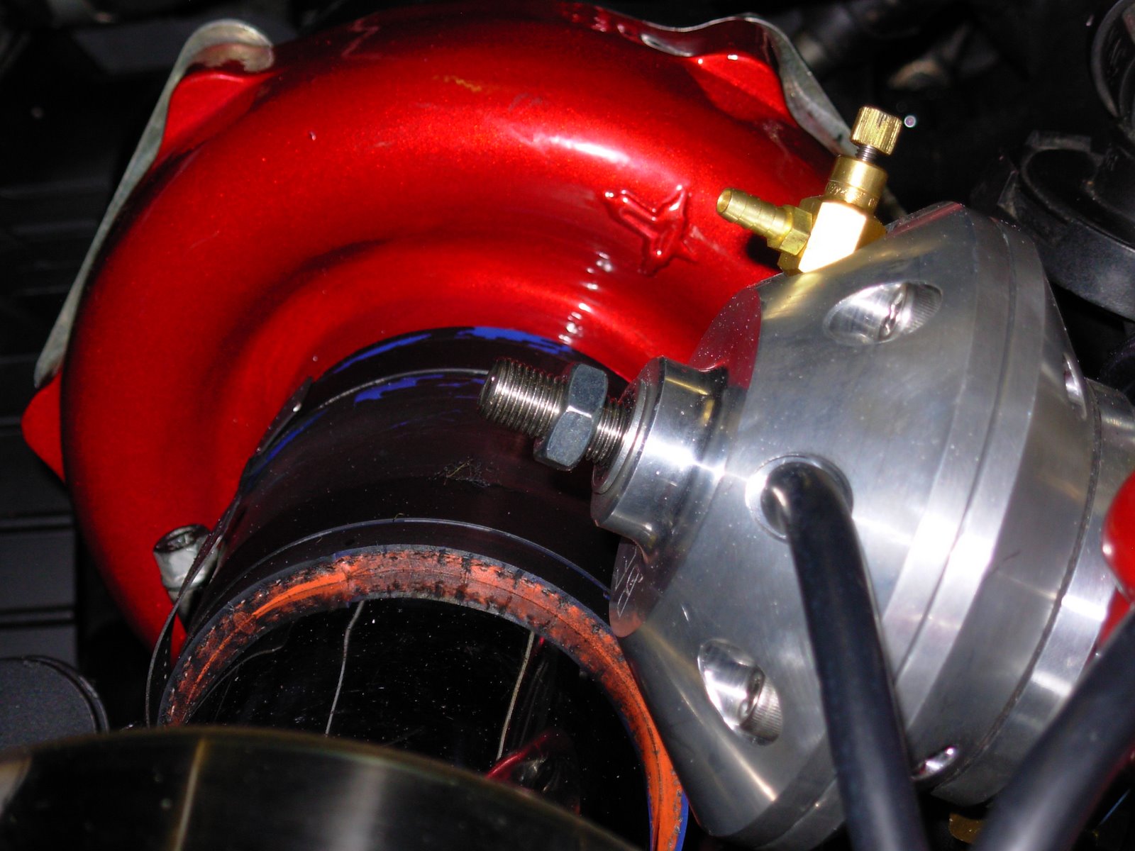 Now is the time to adjust fuel, I loosened the lock nut on the Fuel Management unit, Or otherwise known as a boost dependant regulator. The big nut controls base pressure ( idle) It needs to be 55 psi. right now its 4 psi, LOL WAYYY LOW! I carefully raised it.
Here is an often overlooked issue. The stock intake had a nipple on it. This is where the crankcase gets its ventilation air from. Its called Positive Crank case Ventilation , just like PCV valve acronym. The air would travel through the air filter and down the intake. There is another nipple that is connected to the intake manifold behind the throttle body. So there is a constant vacuum, the air is sucked through the nipple attached to the intake, through the engine and into the intake. Without a breather ( small air filter) you are sucking in unfiltered air and will get crud in your oil in a hurry and increased oil consumption.

Here's me doing that screw thing. I also hooked up the Signal lines ( vacuum/ boost hose) One hose runs from the tial waste gate to the nipple inlet on the fuel regulator, In the middle is a T that connects to the turbo compressor fitting. This is where the boost signal comes from. Make all these lines short as possible.

The spring is 2.5 in wide so you will need to depress the spring to install the top back on. It take about 20 pounds of pressure to do this. I recommend holding it down and putting one screw in each side and let the screw driver do the rest. Pushing that hard for a few minuted get old quick! Tighten all the bolts down, don't worry they don't make a air tight seal. No sea lent needed. Its just holds the spring on.

Here is the 5.25 Small red Spring. I had a fit when I purchased it I thought they sent a 15 psi Large spring. I am told they war only a 1/2 in difference in size. Anyways make sure to install this thing with the colored side up.

Here is the Tial Waste gate open. This is the 38mm version if anyone wants to know. This is what the inside looks like. You can see in this pic the whole that I couldn't get the bolt into. I will make the shop do it mua ha ha.

I now must unscrew all these nuts to get the wastage open. There is no control spring inside yet. I have two springs 5 psi and 7.5 psi. I am putting in 5 psi for right now until I get injectors in. I estimate I can make around 215 HP at 5 psi Boost.
 Woo! Okay wells that's all the installing I am doing right now. Remember that I already had the Fuel pump, Oil line and fuel line installed before. The only thing I couldn't do is get a bold in the left side of the waste gate. It just wouldn't line up. i am going to let a shop deal with it. preferably the one that made the down pipe.
 Piping done, I painted it black , looks good. I used three clamps on the upper hose because the angle is not perfectly straight so I put two couplers on the side that is tilting a bit to insure a good seal.

Top and bottom piping made very close together.
 I realized the coupler I had was different on each end. One end being longer. I switched it around and about had a hear attack! There was just enough clearance where nothing rubbed. WOO! The coupler had split the night before, so I filled the crack with rubber compound and tightened a clamp over the break itself, after it dried I just left the clamp for support. Oh and I wrapped the whole thing three times with electrical tape for overall support. That tape is very strong and pulls tighter than any other tape. It worked well and held up fine. I will buy another one of these days as a replacement.
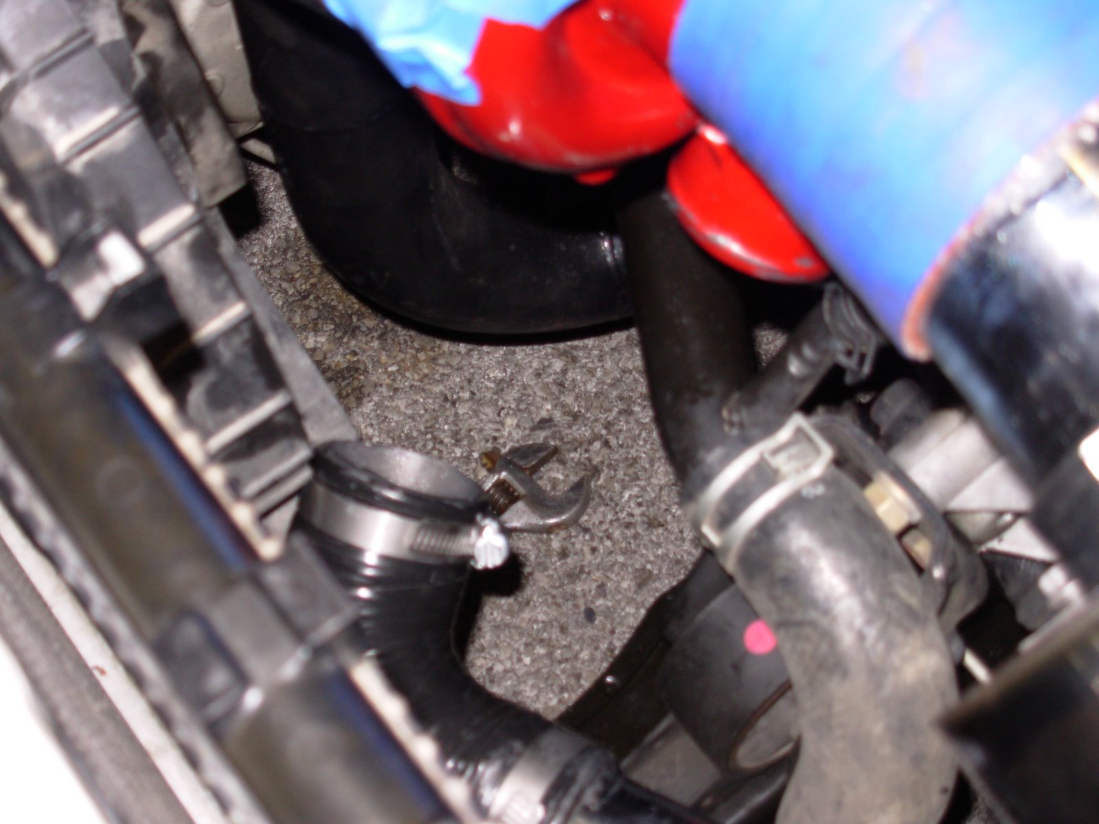 This was truly the hardest turbo coupler evarrrr! It fit so tight against our other pipes that the sealant acted as a lubricant and would slip off a few minutes later after screwing down the clamp. I tried to Hold it on with duct tape till it dried then tighten it down the next day. As you can see that didn't work. However now the sealant was dry.
 I realized the intercooler lower nipple was 1/8 in larger than the other. The couplers I had simply wouldn't fit and that's a really odd size. I went to autozone and purchased a heater hose rated at 45 psi. this should do the trick, and it did! I cut a section of the hose and coupled it on with three worm gear clamps.
 I applied sealant to the coupler as it would suck for this one to pop off as the battery must be removed to install it. I kept the blue take on to prevent scratches
 This is the custom bent Intake pipe that spans from the Intercooler to the intake manifold. The red piece is the HKS Blow off Valve. It has a long mouth so I could make it a recirculation valve. That just means that the air pushes back into the intake of the turbo to keep vacuum to a minimum when shifting gears. This is done on the stock GS-T.
Intercooler test fit, I may need to trim a portion of the bumper later, I will avoid it if at all possible. If I do It will be minimal.
 Intercooler installed, This is the basic placement. I end up taking it off again when I connect the lower pipe because there was hardly any play in the piping system.
 Here is me, Still working off those Thanksgiving pounds. I am adjusting the intercooler here.
 There is a Air dam plastic behind the bumper. This stuff is very thin. Thinner than a coke bottle plastic and if you grab it and pull it tears off. I ended up removing the whole thing after removing the inner bumper.
 I removed the front bumper here to install the intercooler.
 Picture Of the car from the front with headlights on, Its like the monster under my bed but this one eats Hondas.
I taped off all the candy red and painted this ugly heater pipe, Maybe later I will cut a piece of hose and cover it up, but paint keeps it from rusting. Always use BLUE painters tape. You will have a rough time working with anything else. The purple stuff isn't sticky enough to stay in place on the powder coated items.

Better picture of the Boost Dependant Regulators New Home. Right in front of the intake.
 I had to install the turbo before the shop would connect the oil line. This is the new home for the fuel regulator zip tied the heater pipe. The shop originally bolted it to the intake mount. Where they thought the intake would go I don't now. Sooooo I did what FIMA should have don't and relocated the little guy and made him a new home by the EGR valve. I am keeping the EGR valve so that I pass emissions. Oh yes I will not have a Check engine light either. Its all part of a bigger plan.
 Removing the waste gate spring for safety in can I need to pull the car forward or out of the garage I don't want the turbo to even think about spinning without the oil line installed yet for turbo lubrication.
Okay its bolted on now. It looks pretty but the heater pipe above the turbo looks horrible. I will paint it later semigloss black. I will paint the thermostat housing too.

Another good shot of the busted gasket can be seen here. At this point I am getting ready to install the turbo manifold. Dont worry I installed the new Stainless steel multilayer gasket. You can plainly see some carbon build up. I am not going to port my head but I would like to clean it a bit. So I scraped away about 50% of the buildup before continuing. Remember manifold bolts dont need that much pressure. Just 15 foot pounds is all you need.
 The exhuast manifold is now apart and the O2 sensor was siply cut off. I didnt take the time the mess with it as there is no plug for the O2 and I did not intend on using the one that was stock so out must it go! Agian it looks like removing the radiator was a good idea to keep from trashing all the little cooling fins while removing the large odd shaped manifold and stock down pipe. The exhaust gasket looks horrible, good thing I have another one, multi layer stainless steel.
 Here is the First Bolt to come out of the Manifold. The Wd-40 did make this much easier as they clearly where getting to the siezing point. Unfortunatly I did not take pictures of the trouble I hade removing the exhuast shield. The sheilds bolts rounded off and where in there really good. I ended up going to home depot and buying a nice chisel and 2 pound hammer. The chisel cut through the heat shield without issues but I ended up wasting a night of work. At this point I did remove the cooling fans, the unbolt easliy and make way for tons of room.
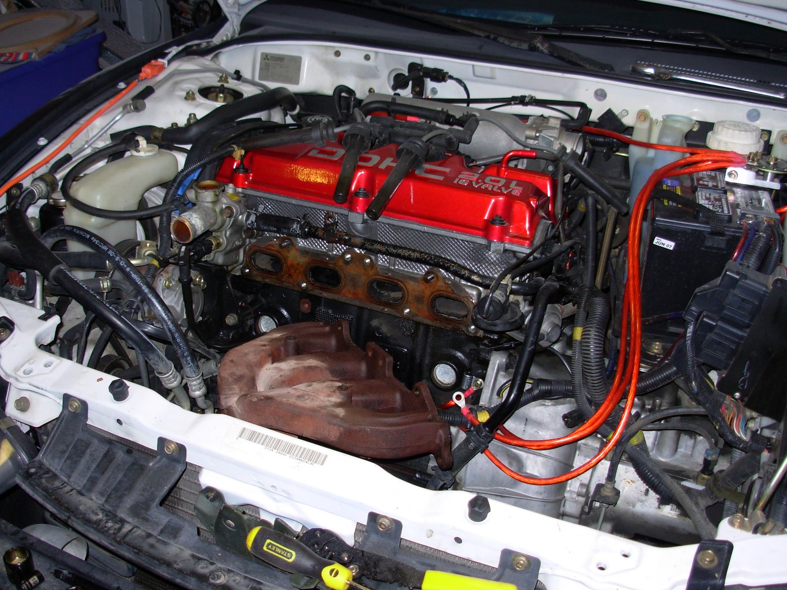
First part installed! I installed the new valve cover and replaced various seals I pruchased from the pars store. I am trying to fix leaks and looks all at the same time. The valve cover looks great here. The "wetness" you see on the stock manifold is from Wd-40. I always lubricate bolts with penetrating oil for a few hours before removing them. I have never had a bolt break on my car yet and I am trying to keep it that way.
 Okay I became a little ancy here. I sat the powder coated parts on the engine just to see what they will look like. The parts are not installed here.
Holding the wastegate up the the turbo. The waste gate need to be welded to the downpipe. It didnt come this way however the car runs much queiter then the waste also travles throught the exhaust and muffler.
 Here is the freshly cut heat sheild for the exhaust side. Just needs a mounting hole ( or 2) and we are in business.
These are the pieces of stainless I cut away from the Steel canister I purchased to make the Turbo exhaust side shield. The steel is fairly this, I will experiment with this material.
 Turbocharger housing already installed on the Turbonetics t3-t4 60-1 turbocharger. The intake is 3 in. the output is 2 in. Here the manifold was sprayed with high temp ( up to 1200 degrees) The purple take it to keep junk, dust or even bolts from making their way into the turbo later on. The turbo is almost new, no shaft play very clean.
This is the powder coating I recieved from my buddy Jeff Ford ( FYI I sell for him if anyone likes my install) All this cost about 300 dollars by the time everything is shipped to him, cleaned, sandblasted, coated, clearcoated, baked and shipped back. Bake on this is two sessions of 14 min. at 425 degrees if I remember right. This is silver metalic that has been coated by a candy red ( transparent) then add clear.
 This is the Layout of the Turbo , Heat shield I made and the Intake for the Turbo. I made the Heat shield from a stainless steel cylinder I purchased for about 6 dollars. This really is a premature pic and is out of chronological order. This happened after the powdercoating. See The powdercaoting write- up to see the before and after for all the coated parts.

Here is the original engine and how it has looked for the last ten years. The only change is a new battery and Red Grounding Wires replacing the smaller orininal counter parts. Its recomended to have at least 5 grounding points in s grounding system. View my writeup on grounding kits for more information there. I descided my accent color for the car will be candy red. Well lets get started.
 This is the Layout of the Turbo , Heat shield I made and the Intake for the Turbo. I made the Heat shield from a stainless steel cylinder I purchased for about 6 dollars. This really is a premature pic and is out of chronological order. This happened after the powdercoating. See The powdercaoting write- up to see the before and after for all the coated parts.
Here is the original engine and how it has looked for the last ten years. The only change is a new battery and Red Grounding Wires replacing the smaller orininal counter parts. Its recomended to have at least 5 grounding points in s grounding system. View my writeup on grounding kits for more information there. I descided my accent color for the car will be candy red. Well lets get started.
| powered by hit-counter-download.com |


No comments:
Post a Comment